Holiday DIY hobby electronics Christmas tree
When I was a kid my dad made me a little blinking "Christmas tree" out of a "cone" from a pine and some little electronics and leds. When last year I saw the nice blinky presents I got together for free when odering from local hobby electric shop I though the next Christmas will be the perfect time for making from that circuit what my dad once did for me as a present for my girlfriend.
Then I thought why not write a tutorial about it so others can build - maybe even foreign people who did not see the Hungarian tutorial for it of course?
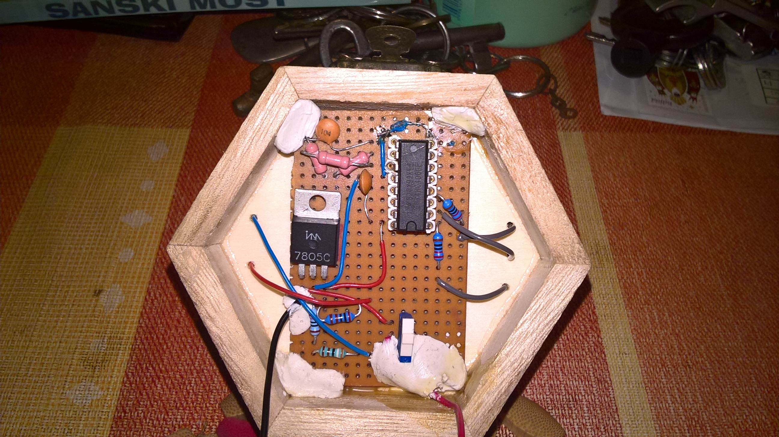
The end result
There is an old saying that if one sees a software developer with a soldering iron, one should expect a run of amok and chaos soon. I hope the end result is a bit better than that, and advise the present as easy DIY project for anyone!
I tried to craft it well and tried to pay attention to detail.

To see it in function, just watch the following short youtube video.
But if you are a Hungarian you might watch the longer educational video!
Influence and motivation
As I already wrote about it, my motivation was coming from two directions. The first motivation was remembering how happy I felt when I was a kid and father gave me his little similar tree he created. I thought my girlfriend who works with small children and studies in fields related to them might as much like the present - and also I thought maybe one day my own kids can see this if I make this well enough so they can also stay amazed at its simple magic.
The second part of my motivation was more like a trigger: When I was thinking about what to give as present last christmas I got this nice free blinky from a well know Hungarian hobby electronics forums store (hestore.hu).
I thought to myself: I see that I can just copy this circuit and put it into a small box that has a cone and leds on it with decorations to remake some similar thing just like my dad made and surely I hope it will be happy present.
As you can see their page already has schematics so one can just build using those and skip reading my blog here, just I made minor adjustments only but here I will present my version with schematics and explanation that might help you if you also have stuff at home but not exactly the same as in the original description (or mine).
What do you need for this project?
Prerequisites
Spend less than 10 euro on the following stuff:
- Soldering iron
- Some kind of probe panel you can solder on
- Cables
- 10 piece leds with different colors
- 2 pieces of 104 nF capacitors
- 2 pieces of 220 ohm resistors
- 2 pieces of 2k ohm resistors
- A 270 ohm resistor
- 3 pieces of 1k ohm resistors
- Some kind of switch
- An LM7805 variant (+5V creation)
- A 74HC4060E oscillator and binary counter IC
- 9V battery
- Connector for the battery
- Glue
- Solder
- Small drill or something to make holes
- A little box
- A pine cone
- Time on your hand
If you have some resistors and capacitors likely you can build it if you read this post carefully as there are multiple ways to do it a bit differently just like how I also do it differently than how hestore people are doing it.
Good to have
These things that are not necessary but good to have anyways:
- A multimeter for testing
- Other decorations as you wish
- Good lights, helpful cutter tools, etc.
- Understanding binary or electronics or anything helpful
- Patience
Light conditions were bad for me, but my cone has pearl decorations and my multimer was helpful when it did not want to turn on. A scope is maybe even more helpful to see if the IC is counting or not, but one should be well without that in these really simple circuits come on (I do not have it).
Basic idea
So the idea is to buy a cheap but nice box (you can make it if you want) and put all electronics inside and to drill holes for cables and make it hole the battery and everything. Then leds are controlled through cables only from the inside of the box while they are on a cone that is glued on top.
What is the basic principles of digital electric operation?
- We create 5V using the 7805 from the 9V battery
- The switch is there so we can turn it off to not drain battery
- The IC counts and we use 3 bits of that for 8 "states"
- The frequency of the IC counting is controlled by an RC circuit
- We use tricks to light various leds for each of the 8 states
Okay. Maybe I go too fast if this is a tutorial and I want literally anyone to get able to recreate it so let us break this down...
Description of the inside parts
In order to follow the text, you better keep looking at this below schematic.
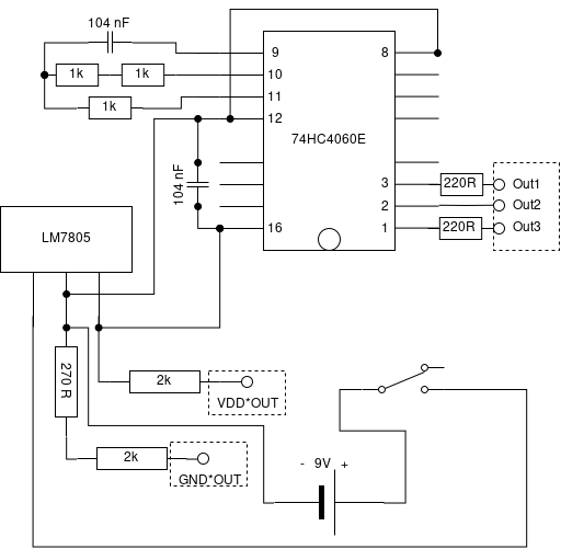
This schematic I tried to completely correspond to the photo about the inside.
Looking at these now we break down the basic ideas a bit.
Creating 5V
So first of all most simple small electronic ICs work with either 3V or 5V but there is usually no battery with 5V. The original hestore cicuit works from getting this 5V from an USB port, but I wanted a mobile solution. This is routinely solved by just employing a 9V battery and use an LM7805 IC which has three legs: The left here is where we put 9V in, The middle is a common 0V which is connected to the circuit 0V and the "minus" of the battery and its third leg of this IC magically creates 5V (and some heat dissipatation). This one is really just that simple.
Adding a simple switch
The switch is just mechanically connects or disconnects the power line of the 9V. Oh and please always disconnect the plus instead of just disconnecting the ground even though that "might work". Bad habit. My case with the switch was that I had no "on-off" switch at home, just one that switch one line into one or the other direction, but leaving out one side of that you get an old boing kind of usual switch out of this. The one I was using would be able to make us choose between two different ways of blinking for example if we would make two different blinky circuit (like an 555 timer based and this one). I did not go that fancy as I like it as it is.
Understanding the binary counter IC
So what is this binary counter IC? It practically counts for us when powered. Not surprising is not it? Still it is good to talk about it a bit more. It has a 14 bit counter in it, so it can count until 2^14-1 for us counting from zero and then starts again circularly until the end of times (or the power).
As with all ICs, one better looks up its datasheet for how it works.
As one can conclude using the datasheet, this is how the digits of the counter appears on the pins of the IC as in the next table.
    | Digit | 13 | 12 | 11 | 10 | 9  | 8  | 7  | 6 | 5 | 4 | 3 | 2 | 1 | 0 |
    |-------|----|----|----|----|----|----|----|---|---|---|---|---|---|---|
    | Pin   | 3  | 2  | 1  | -  | 15 | 13 | 14 | 6 | 4 | 5 | 7 | - | - | - |
To explain this a bit more, we can say that when counting is at zero all the 3,2,1,15,13,14,6,5,4,7 pins are 0V and when counting is at 100 (dec), which is 1100100 in binary we get voltages as in the below table.
    | Volts | 0V | 0V | 0V | 0V | 0V | 0V | 0V | 5V| 5V| 0V| 0V| 5V| 0V| 0V|
    |-------|----|----|----|----|----|----|----|---|---|---|---|---|---|---|
    | Pin   | 3  | 2  | 1  | -  | 15 | 13 | 14 | 6 | 4 | 5 | 7 | - | - | - |
As you can see some binary digits are just not having pins to go outside of the IC we have but part of the counting still. This is fine. Also it is clear here that as it is usual in digital circuits +5V acts as logical one. Usually in most cases the logical one is the voltage of the circuit.
We can also understand now that pin 1,2,3 digits change much more slowly than pin 7,5,4 digits (because they being higher digits). Namely 2^8 so 256x more slowly but following the same patterns while counting because we always count one-by-one all the time. You can think about this or write down it on paper.
The basic idea is that we use 3 consecutive bits of this counter using the pin layout and that way we get a smaller counter that counts from 000 to 111 in binary. That way we end up having 8 separate "states" and this is why we drill three holes on our box with 3 "data" wires to go though and 2 "plus & minus" wires. On the top we connect these to leds.
Understanding the RC oscillator setting
So what we did not tell about our IC? That it is nost just a counter, but also an oscillator too! This just means that it can actually can count on its own, by setting a oscillator frequency - practically the frequency of the counting. By defining this, we can make the counter count faster or slower as we want it.
There are many ways this can work and even the IC supports more (like using cristals), but the simplest is just use RC oscillation. This is called RC because one can use Resistors and Capacitors for defining frequency.
We will not delve into RC details, but page 15 of the data sheet explains how to set the oscillator frequency. We need to put R1 R2 and C1 so two resistors and a capacitor/condensator on the 10, 11 and 9 pins respectively.
Then frequency will be around 1(2.5 * R1 * C1) given that we apply some minima.
If you look at the circuit the hestore guys made, you will find that they use 470k ohm resistors both for R1 and R2. I did not have those at hand and could not go into shops in my area that sell them. You of couse can put other kind of resistors serial or parallel until desired results but my problem was that not only I did not have 470k, but nothing even close! All I had (after making other resistors as close as they can be) were 1k resistors from which I had a lot but not 470 of them to make it a serial 470k one haha.
There are multiple ways to circumwent this! My first temporal solution was to actually use a big electrolytic condensator/capacitor that was getting me the same frequency. As you can see this is doable, but it is not the best thing to put electrolytic capacitors in this small present as they will surely wear out after enough time passes for them and blow into small pieces.
I have found a better solution: Just added two 1k resistos (forming 2k added) as my R1 variant and kept R2 as a single 1k resistor and used the 104 nF C1. But as this would lead to a much faster counting circuit - actually so fast that one cannot even see, just dimmed leds if lucky at all - I decided to use pin 1,2,3 instead of the lower digits that hestore guys used as these change in the same pattern as theirs, but 256x slower. The original R1 was 470k and mine is 2k, so we count 235x faster, but I use digits which are changing 256x slower thus negate this effect completely.
At least now we do not need to think about if we accidentally put in the electrolytic capacitor reversed as the small ceramic ones can be put in any ways we want to without them blowing into useless pieces...
Connections to the outside parts
On the schematic above I tried to mark it clear where cables go out of my box. These are Out1, Out2, Out3 and VDD¤OUT, GND¤OUT. The latter two are marked because they are not really just ground and 5V but through resistors. Also after the outputs of pin 1-3 of the counter IC there are resistors too.
Explanation for those follow later.
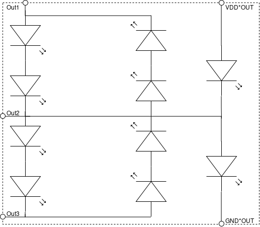
Description of the outside parts
One of my goals were that outside the wooden box I want to minimize circuits except leds and of course the cables that connect them. For this I ended up having this part on the outside - I marked where we connect with the inside.
Hestoreplexing
If you read about the original hobbi elektronika page they write that they use "charlieplexing" to drive leds with only a few pins. Charlieplexing however works by using that not only 0 and 1 can be a pin but one can sometimes set it as an input pin in case of microcontrollers and that is like as if we would cut its wire (high impedance state).
This makes a difference and not the same as it being 0V! Just think that we have pin1 as 0V, pin2 as 5V and pin3 in "high impedance" in the above outside schematic part. The leds get power differently in those cases!
Charliplexing is using this up so one can drive many leds (or do other stuff). What we have here is not charlieplexing, but similar. It might be better to even forget what charlieplexing is as looking it up might confuse you!
What we do here is that we just have a counter whose pins are eiher 0 or 5V. A led is a diode (Light Emitting Diode = LED) so lets through current only in one direction which is marked as the arrow direction in the schematic. This already defines that some leds do not light up when a pin is on as current just cannot flow.
An other thing to know is that current does not flow when there is no potentia difference that enables the flow. So if the middle pin is 5V and you see Vdd coming from the top right of the schematic the the led below VDD¤OUT will not light up because electricity is like water: it will not flow where there is already filled amount in the "pipe" (here cable).
One third thing plays here: It is that leds cannot just driven by 5V and they actually might get damaged and killed by that. We need to put some resistors in series with them to control how much they tolerate. If you can access the datasheet for your leds you can even see tables and graphs about when the LED will start to dimly glow, when it is too much for them (maybe not talking in volts but in small ampers - but you can calculate with equations).
The resistors for making the LEDs save are in the inside of our wooden box for keeping the beauty of the product, but understanding how this "hestoreplexing" works is best if I add them to the picture! The key is that if the resistors in the circuit path the electricity passes through are too low, the current will of course flow through the LED (if in the good direction of diode), but the current will be too small to light up a LED (maybe some lucky animals can see the light, but not us humans).
So this is different from Charlieplexing as we are not tricking with putting a leg of a micocontroller into input to make it look like it is cut from circuit, but use other tricks that leds will not light up, despite current flow through as the amount will be too small for visible resuts. This way we can light up multiple leds in groups without doing what charlieplexing people do: that we do not need to light up a led for really short time, then the other, then the third so fast that human eye thinks all of them light simultenously as they do really light simultanously - just some also "light" without us seeing it.
From this point the planning is about making resistos that make the relevant leds light up exactly when we want them to be lit.
I made a small gif animation for how it works:
The part of the circuit that is outside the box are marked with dot-grouping.
If you try to imagine current as if it would be flow of water in pipes it is not that hard to grasp from that point onwards. When all outputs are low (0V) only led9 lights as there is VDD above it and it directly connects to the middle 0V. This is the "path of least resistance" so most flow goes here. When the first output is one (+5V) two leds between that and the midle zero volt is lighting up - alongside with the led 9. So leds 1, 2 and 9. Led 10 will not as the midle line is zeroed fast and with practically no resistance, but in the thirds state (when midle is the +5V) the led9 finally stops as there is a big +5V in the midle so there cannot be flow from that diode as the mid is already filled but there are flows in two-two leds towards top and bottom and also led 10 lights now and so on and so on. Led 9 only lights when the middle output is low and led 10 only lights when it is high as you can see.
With similar basic thinking about path of least resistances, thinking and the potentia-differences or not - are enough to save you calculations actually.
Mistakes I made
My first mistake was that I thought I bought everything I need and had to make changes to the original schematic to make it work. At least maybe someone will be able to learn something useful out of them.
My bigger mistake was a cable. I used a cable piece that was already cut and it was the only one I did not cut myself. This was for connecting pin 8 and 12.
It turned out the cable was bad and was not connecting. I have found it out by accident, but when I first turned on my completed making only one led was lit and nothing was bliky or moving. I went with my multimeter and checked if my solder connections are good or not by using the setup on the multimeter that makes a sound on a good connection. I heard it is not making a sound there then I held a wire by hand to connect it and it just started working. Also I have found that if I move the originl cable enough it works too so it is a concact error of the broken cable.
I was thinking about how to solve this. I was doing soldering that way that all soldering is on the back of the panel and the IC legs go through the holes of the panel then the cabls go through a nearby hole and I connect them on the other side which has copper coating. But to make it like that I would need to remove the panel which was already in place... It was not glued, but I would still had to cut 3+2 output wires, then fix it, then join those.
Instead of that I chose to cut the wire where it was too long and was bad and cut a small enough wire and solder it right against the leg of the IC holder on the top side of the panel (the IC still is changable). The other side I have just soldered against the cut wire part which was not bad - it was two pieces earlier anyways. I saw a "solution" like this on pictures about old 8 bit controller motherboards where they added an extra address line for RAM.
Further advise
It is highly advised to glue in the cables that way to the box so that the lid can both open completely without breaking them, but all cables automatically fit into their place when closing the lid and never gets crushed by the lid.
If you can, you should put the switch outside. I only had a small dip switch that is only stable if I solder it in. I made it even more stabilized by me utilizing its unused and used legs and bending them below the panel to hold the switch in place mechanically.
Try to think in components: I made the RC circuit fit into its place, then I soldered all the stuff around the LM7805 and the switch, then I added the I/O connections and their stuff towards the outside parts. Much better to check back your work if you do not do all the whole at once! Also I created the outside part on the cone completely separately before I soldered the two together and glued the cone. Also first did not glue, just I cut the panel it that way that it was not moving even if I not glue it and is hard to fall out. These were all good ideas.
When adding the leds I did not even glue the leds. I just bent their legs in opposite directions as if a led would "hug" the piece of the pine cone.
Before randomly putting the leds up, try to imagine how the wires will look! This is actually crucial for a good results, but it is fine without it too. I have spent most of my time thinking about the "topology" of wires and leds. I wanted to make the ones light up the same time far fom each just like the hestore guys did, but also wanted to not have a cable mess. I deciced to put the blue led - the one closest to "VDD¤OUT" first on the top, then its GND counterpart green led in my case. These were just an up-down going through the little tree I made. Later leds I was making circles around the tree, with going top to bottom on the schematic and putting leds in the same "circling" with little spicing up to move them further when when they were in the same vertical colums on the schematic of the outside parts. Then these circlings were connected in their middle to the middle pin output where I could do.
Final words
I think this post will be double-edged: some people will say that "of anyone can blink 10 leds" and that all I did was to make an already existing idea having some sugar-coating and a unique build. But hey! Those things count too! Also some will maybe complain that this is less deep than reversing an old dos game and hacking it or speeding up a blog or doing multithreaded stuff. Yet there will be those of my readers who are strictly software guys and for them some parts of this might be hard to understand. Originally when I was doing tutorials on assembly in the old times I always tried to write for anyone to understand it and many was happy for that. I am not usually aiming for this anymore on my blog unless there is a possibility for that. But when talking about a DIY chrismas gift? This approach of similicity is the best! Also it took actually pretty much time of my life around pre-christmas nights to prepare all of this post and videos. Trying to make some not so clever but normal thing understandable by the highest number of people who might visit the blog can lead to as much time being spent on the content and its quality that it mirrors some of the more hardcore posts.
I think those who have a relevant IT experience will be able to hopefully grasp most of what is written here and hopefully even those who do not - can still be able to at least just copy the circuit with enough time on hands.
Schematics were made with draw.io which is free and was usable for this.
Tags: DIY, Christmas, electronics, hobby, present, tutorial, tree, blinking, circuit, beginner, hestore, hestoreplexing, charlieplexing